Category Archives: Oil & Gas

Wellbore Perforation

Wellbore perforation is a stage of oil well completion; it provides a direct link between

the wellbore and the oil formation through perforation tunnels and the surrounding cement sheath. The quality and quantity of the tunnels have a direct influence on well productivity. Therefore it is crucial that completion engineers should ensure that wellbore perforations are located in the right places, oriented correctly, deep, and clean. Effective perforation design and execution process facilitate natural flow and easy pumping of oil, exclude water from the overlying or underlying units, and keep formation rock particles out of the well.

Process

In order for a wellbore to be productive, the casing and cement are perforated to allow the oil and gas to enter the wellstream. In case of cased-hole completions, casing is required to be run into the reservoir. Perforating equipment are transported to and operated at the site by a specialized crew. The tools are then assembled upon arrival to the site. A wireline, slickline, or coiled tubing runs a reservoir-locating device and a perforation gun into the wellbore. Upon reaching the perforation reservoir level, the gun shoots holes to the sides of the well to allow oil and gas to enter the wellstream. Perforations are created by either firing bullets into the sides of the casing or discharging jets/shaped charges into the casing.

Locations of perforations are determined previously using drilling logs, although intervals cannot be easily located through casing and cement. To solve this problem, a gamma ray collar – correlation log is implemented to correlate with the initial log run on the well and define the locations where perforation is needed.

Potential Hazard

Perforation almost always involves use of explosives, and surface detonation poses a great risk to the lives of drillers. Before starting the perforation, keep all non-essential personnel out of the site and post warning signs. Prohibit the use of communication gadgets or navigational systems, and shut down non-essential electrical systems during gun-arming operations. Operations involving explosives should only be performed under the direct supervision of the special services supervisor. Remnants of explosives should be reported to the aforementioned supervisor.

References:

Behrmann, Larry, and Chee Kin Kong. “The Search for Perfect Perforations.” Schlumberger. Schlumberger Limited, 2014. Web. 19 Dec. 2014. <https://www.slb.com/~/media/Files/resources/mearr/…/perforations.pdf>.

“How Does Well Completion Work?” Rigzone. Dice Holdings, Inc., 1999. Web. 19 Dec. 2014. <https://www.rigzone.com/training/insight.asp?i_id=326>.

“Oil and Gas Well Drilling and Servicing ETool.” Occupational Safety & Health Administration. U.S. Department of Labor. Web. 22 Dec. 2014. <https://www.osha.gov/SLTC/etools/oilandgas/servicing/special_services.html>.

Cementing the Wellbore: Cementing Operations (Part 2)

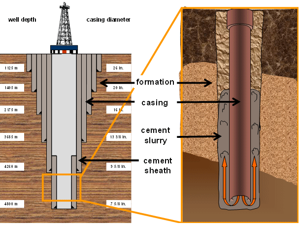
A steel pipe, or casing, is run into the wellbore before an L-shaped cementing head is fixed on top of the wellhead to receive the slurry. Two wiper plugs, the top and bottom plugs, sweep the inside of the casing and prevent the slurry and drilling fluids from mixing.

The bottom plug is introduced into the well before the slurry is pumped into the well behind it. The bottom plug, which works as a one-way valve that allows the slurry to enter the well, is caught just above the bottom of the wellbore by the float collar.

As cement is pumped into the wellbore, pressure is increased until a diaphragm is broken within the bottom plug. This allows the cement to flow through the casing and up outside the casing string. After the proper volume of slurry is pumped, a top plug is pumped into the casing to push the remaining slurry through the bottom plug. The pumps are turned off once the two pumps reach each other, and the slurry is allowed to set.

Pumpability time is the amount of time it takes for the slurry to set. Special types of cement are used to set wellbores at deep depths, under high temperature and pressure, and in corrosive environments.

Reference:
“How Does Cementing Work?” Rigzone. Dice Holdingd, Inc., 1999. Web. 19 Dec. 2014. <https://www.rigzone.com/training/insight.asp?insight_id=317&c_id=1>.

Cementing Operations (Part 1)

Cementing is another stage in well completion that prepares a wellbore for further stages. The operation mainly involves development and pumping of cement into place to protect and seal the wellbore. This way, non-hydrocarbons, especially water, can be prevented from penetrating into the well.

Cementing is used for other purposes, to seal the annulus after a casing string has been run into a well, to seal an area where flow has been reduced or absent (also known as lost circulation zones), to plug an existing well to control its flow, and to plug an abandoned wellbore.

To displace existing drilling fluids and to fill in the space between the casing and the sides of the drilled well, cement slurry is pumped into the well. The slurry is composed of a special mixture of additives and cement, and is left to harden to seal the well from non-hydrocarbons that might try to enter the wellstream. This is also to ensure that the casing is positioned permanently into place.

tbz1e

Cement Preparation

To determine the amount of cement needed, the diameter and the depth of the borehole are measured using a caliper log. Multifinger caliper logs measure the diameter at various locations using mechanical and sonic means to accommodate irregularities and to determine the volume of the openhole.

The required physical properties and proper set of cement are also put into consideration before starting the cementing and pumping operations. Special mixers are used to combine dry cement with water like hydraulic jet mixers, batch mixers, or re-circulating mixers. The result is wet cement known as slurry. Portland cement is used in this process and is calibrated with additives to form one of the eight different classes of cement which is set by the American Petroleum Institute (API)

There are various types additives mixed into the slurry: accelerators can shorten the setting time for the cement, while retarders can prolong its setting time. On the other hand, lightweight and heavyweight additives can decrease or increase the density of the slurry. Other additives can transform the compressive strength of cement, its flow properties, and its dehydration rates. Bridging materials are added to plug lost circulation zones and antifoam additives are included to prevent foaming within the well. Cost reduction efforts call for the use of extenders.


“How Does Cementing Work?” Rigzone. Dice Holdingd, Inc., 1999. Web. 19 Dec. 2014. <https://www.rigzone.com/training/insight.asp?insight_id=317&c_id=1>.


Well Logging (Part II)

Types of Well Logs

Various types of well logs have emerged over time due to technological improvements. Different tools are used to measure and determine subsurface characteristics.

Resistivity Logs measure electrical flow through rocks and sediments. This log determines the types of fluid present. Formation waters are salty and are good electrical conductors, whereas oil and fresh water are poor electrical conductors.

Induction Logs assess the interaction of magnetic force and electric flow to determine resistivity. They are used for oil-based drilling or air drilling wells, which are non-electrically conductive, unlike mud or water wells.

Spontaneous Potential (SP) Logs calculate electrical currents generated between drilling fluids and formation water held in the pore spaces to show the permeability of rocks in a prospective oil well. SP logs are referred to many times to determine whether a rock formation is a shale or a sandstone.

Well Logging Methods


Mud Logs refer to the drilling of fluid or mud to provide buoyancy to the drill and to remove cuttings from the well. Together with the driller’s log, evaluation log, cuttings log, and logs of nearby wells, information from mud logs is used to determine the commercial viability of an oil well.

To retrieve data before, well logging tools were used to be lowered into the well for regular intervals. Directional drilling have pushed scientists to develop non-vertical methods of well logging. With Logging While Drilling and Measurement While Drilling (MWD), logging tools can now be placed at the end of the drilling column so drillers can determine the prospect of an oil and gas well.

As technology makes more headway at this present time, well logs are now computer generated to interpret gathered information immediately while drilling. These logs are sophisticated that not only they can record measurements, but they can also notify drillers of a potential hazard and can transmit data to offsite servers through satellite.

Potential Hazards

Because logging involves tools that are radioactive, electric, and/or sonic in nature, a driller may be at risk of radiation exposure. At best, drillers should wear appropriate personnel protective equipment (PPE) when using the tools. Authorized and qualified personnel should only be the ones allowed to handle logging tools, while other non-essential workers should be kept away from the rig floor and marked-off sites where radiation hazards may be present. Damage to any radioactive logging tools should be reported immediately.

Other drillers can also get injured by unexpected pressure release. To minimize this occurrence, it is highly advisable to check for the presence of trapped pressure before the tool housing is opened.

References:

How Does Well Logging Work? (1999, January 1). Retrieved December 19, 2014, from https://www.rigzone.com/training/insight.asp?insight_id=298&c_id=1

Oil and Gas Well Drilling and Servicing eTool. (n.d.). Retrieved December 19, 2014, from https://www.osha.gov/SLTC/etools/oilandgas/servicing/special_services.html


Well Logging (Part I)

Well logging records the events, subsurface formations, and depth measurements of geologic formations during drilling. Each well log is a detailed record which can include visual observations (geological logs) or physical measurements made through instruments (geophysical logs) penetrated through a borehole. Some types of geophysical logs can be recorded during any phase of an oil well’s life, namely drilling, completion, production, and abandonment. The concept is borrowed from ship logging in which events aboard a vessel are recorded. But instead of plotting a timeline, well logging is recorded through depth.

History

In the early 19th century, well loggers scaled oilfield derricks and kept a simple chronicle of events that happened at certain depths, which include problems, types of formations encountered, drilling speed, and oil and gas flows.

In the early part of the following century, Conrad Schlumberger envisioned the use of electrical measurements to scale and map out subsurface formations. He and his brother Marcel eventually performed the world’s first well log in France in 1927 using resistivity, a measurement of how strongly a given material opposes the flow of electric current. century, well loggers scaled oilfield derricks and kept a simple chronicle

Method

A graph and corresponding notes represent drilling records and well depths. Logging tools are inserted into the well to measure the electrical, acoustic, radioactive, and electromagnetic properties of subsurface formations. To collect data, logging tools are incorporated into the drilling tool or drilling tools are lowered into the wells at regular intervals.

Drillers and engineers use well logs to measure formation thickness, formation tops, porosity, water saturation, temperature, types of formations encountered, presence of oil and gas, estimated permeability, reservoir pressures, and formation dips. Well logging does not only record wellbore events, but also ultimately predicts whether a well is commercially viable or not, and whether casing, cementing, and completion should be run on a well.

Reading a Well Log

A well log includes a header that provides specific information about the well like the operating company and the type of log, as well as the main log section and the graph. The vertical part of the chart represents the depth reached, while the horizontal part represents the measurement scale.

Each major section of the log contains inserts which identifies each curve. Curves on the logs – called traces, readings, or measurements, can be represented by solid, long-dashed, short-dashed, or dotted lines to represent different measurements used on the log. To ensure accuracy, the final part of the log includes the tool calibrations used before and after the log was conducted.

References:

Helmenstine, Anne Marie. “What Is Electrical Resistivity?” Electrical Resistivity Definition. About Education, 11 June 2014. Web. 19 Dec. 2014. <http://chemistry.about.com/od/chemistryglossary/g/Electrical-Resistivity-Definition.htm>.

“How Does Well Logging Work?” How Does Well Logging Work? Rigzone, 1 Jan. 1999. Web. 19 Dec. 2014. <https://www.rigzone.com/training/insight.asp?insight_id=298&c_id=1>.

“Oil and Gas Well Drilling and Servicing ETool.” Oil and Gas Well Drilling and Servicing ETool. Occupational Safety & Health Administration. Web. 19 Dec. 2014. <https://www.osha.gov/SLTC/etools/oilandgas/servicing/special_services.html>.
Wireline Operations

Wireline operations are part of special services in the oil and gas industry. The operations include slicklines and electric lines utilized for perforating, logging, bailing, downhole tool setting, fishing, swabbing, and other workover efforts.

Wirelines

A wireline, also called electric line, is an electric cable used to transmit data regarding the conditions of the wellbore and to lower tools into it. It may consist of single or multi-strand cables that are braided. Aside from gathering data for other workover tasks, wirelines are also used to perform wireline logging.

Slicklines A slickline is a thin non-electric cable inserted into a well to deliver and retrieve wellbore tools like gauges, plugs, and valves. It can also be used to adjust valves and sleeves located downhole, and to repair tubing within wellbore. Wrapped around a drum at the back of a truck, the slickline is raised and lowered into the well by reeling the wire in and out hydraulically.

Wireline Logs

Wireline logs measure properties of well formations using electric lines. They were first developed by the Schlumberger brothers in 1927. Wireline logs are constant downhole measurements sent through wirelines to help drillers, engineers, and geologists make real-time decisions about drilling operations – quite different from MWD and mud logs. Wireline logs assess wellbore dimensions and sonic properties, and can measure conductivity, resistivity, and formation pressure.

The logging tool called a sonde is located at the bottom of the wireline. Measurements are taken by lowering the wireline to the prescribed depth and then raising it out of the well. In an effort to sustain tension on the line, measurements are continuously taken on the way up.

Workover Operations

Workover operations cover remedial work to sustain, restore, and/or enhance production. Although frequent, but not necessarily always, workover operations require production shut-in. a well-servicing unit is used in workover operations to haul things in and out

Special Service Operations Safety (Part I)

What are wireline operations?

Wireline operations are part of special services during the completion and production of oil and gas wells to serve several purposes like equipment transport, swabbing, reservoir evaluation, logging, well intervention, perforation, pipe recovery, downhole tool setting, and bailing. They include both electric and slickline operations.

What is the difference between electric lines and slicklines?

Electric lines are cables that gather and transmit data about a well; they consist of single or multi-
strands for well intervention and formation evaluation. In contrast, slicklines are single-strand non-
electric cables for placing and recovering wellbore equipment like gauges, plugs, and valves. They can also be utilized for tubing repair in the wellbore and for valve and sleeve adjustment in the downhole.

How to prevent masts or booms from toppling over?

It is always important to install foundations, guying, and outriggers according to the recommendations of the manufacturer.

A co-worker was suddenly exposed to an unexpected release of pressure. What are the possible steps to be done?

Install a pressure-release valve in the lubricator sub before bleeding pressure from it. Break the connections and look out for an unusually tight connection. It may indicate that pressure has not been released.

What are the measures that could be implemented to minimize hand injuries and sprains?

Encourage workers to practice proper hand placement and taglines to prevent pinching hands. If possible, minimize handling lubricators and other equipment manually to avoid overexertion.

What is well logging?

Well logging is the identification and recording of information regarding subsurface geologic formations. It includes well bore properties; mud records; cutting analysis; drill stem tests; core analysis; and electric, acoustic, and radioactivity procedures. Tools utilized for well logging include mechanical, electrical, radioactive, and sonic tools.

What are the potential hazards of well logging and how to prevent them?

As mentioned, some tools can expose a worker to radiation. Injuries could also occur due to unexpected release of pressure. It is very important to ensure that workers wear appropriate personal protective equipment (PPE). Logging personnel who are duly authorized and qualified should only be allowed to handle logging tools. Should any radioactive tools be damaged, report immediately. Keep non-essential workers away from the rig floor and marked-off areas of radiation hazards.

Oil and Gas Waste Haulers

Who is an oil and gas waste hauler?

Any person who transports oil and gas waste for hire by any method other than pipeline, such as hauling flowback water via truck.

What is oil and gas waste?

Waste resulting from activities associated with the exploration, development, or production of oil or gas. Oil and gas waste includes salt water, brine, sludge, and drilling mud. It also includes waste materials generated during drilling, operation and plugging of wells such as domestic septage and trash.

What permits are needed for oil and gas waste haulers?

Oil and gas waste haulers must file Form WH-1: Application for Oil and Gas Waste Hauler’s Permit with the Railroad Commission of Texas (RRC). The application must be approved and a permit application fee must be paid. Haulers must register and properly mark their vehicles. Each vehicle must be operated and maintained in such a manner to prevent spills, leaks and other discharges during transportation. A copy of the permit must be kept in each vehicle as identified in the permit application. Oil and gas waste haulers must keep waste manifests to document proper disposal of wastes. You can download the application form (WH-1) and other applications from the RRC website. Based on the waste hauler FAQ guidance at http://www.rrc.state.tx.us/media/8672/waste-hauler-2012-faqs.pdf, forms WH-2 and WH-3 are also required.

Where is disposal of oil and gas waste allowed?

Oil and gas waste haulers must ensure the waste is disposed of at an authorized facility. The disposal facility used by the hauler must be documented in the waste hauler’s permit. Waste generated from oil and gas operations may be disposed of at authorized RRC facilities or certain TCEQ regulated landfills. In order to dispose of oil and gas waste at TCEQ Municipal Solid Waste (MSW) landfills, the waste generator must obtain a special waste authorization by completing and submitting Form 00152 to the TCEQ. Contact your local TCEQ regulated landfills for specific information on types of waste they are permitted to accept. Transporters and generators must keep manifests to document proper disposal of waste. More information regarding disposal regulations is available in TCEQ’s publications titled Disposal of Special Wastes Associated with the Development of Oil, Gas, and Geothermal Resources (RG-003) and Common Environmental Requirements for Regulated Oil and Gas Operations (RG-482).

Who enforces the rules?

State and local agencies are authorized to ensure compliance with applicable waste hauler regulations. State agencies with jurisdiction include: Texas Department of Public Safety, TCEQ, and RRC. County sheriffs and city police departments may request compliance documentation from waste haulers and are authorized to issue civil and criminal penalties, which may include monetary fines, and may impound unauthorized or improperly operated vehicles.

How are truck wash facilities regulated?

RRC has jurisdiction over wastes such as vacuum truck rinsate and tank rinsate generated from:

  • oil and gas exploration, development, or production sites
  • a facility operated by an oil and gas waste hauler permitted by the RRC
  • a facility such as a warehouse, pipeyard, or equipment storage facility belonging to an oil and gas operator and used solely to support that operator’s oil and gas exploration, development, or production activities

The TCEQ regulates rinsate from vacuum trucks generated at commercial service company facilities such as truck washing operations, or companies that provide equipment, materials, or services to the oil and gas industry if the facility is not operated by an RRC-permitted waste hauler. Examples of commercial service company facilities include facilities that provide drilling and work over rig rental and tank rental services, equipment repair services, drilling fluid supply services, and acidizing, fracturing, and cementing services.

Oil & Gas Exploration and Surface Ownership

Questions and concerns frequently arise when owners of residential property in suburban and rural areas discover that oil and gas operations are being conducted in the vicinity. Although the Railroad Commission of Texas generally lacks jurisdiction over these issues, the information below is intended to provide general answers to some of the most common questions.

Mineral & Surface Estates

Under Texas law, land ownership includes two distinct sets of rights, or “estates”: the surface estate and the mineral estate. Initially, these two estates were owned by the same person and they may continue to be owned together by one person. However, in many areas of Texas, especially those where there has been extensive historical oil and gas development, it is common for the mineral estate and surface estate to be owned by different people. The division, or “severance,” of the mineral estate and surface estate occurs when an owner sells the surface and retains all or part of the minerals (or, less commonly, an owner sells the minerals and retains the surface). If an owner does not expressly retain the minerals when selling the surface, the mineral estate he owns automatically is included in the sale.

Dominance of Mineral Estate

Regardless of whether the mineral estate and surface estate are held by one owner or have been severed, Texas law holds that the mineral estate is dominant. This means that the owner of the mineral estate has the right to freely use the surface estate to the extent reasonably necessary for the exploration, development, and production of the oil and gas under the property. This right to freely use the surface estate for the benefit of the mineral estate may be exercised by a company or individual that has taken a mineral lease from the actual owner of the mineral estate. The company that takes a lease and actually operates the property is frequently referred to as the “lessee” and the mineral interest owner who granted the lease is the “lessor.”

Lessees have broad rights to use the surface for the purpose of exploring for and producing oil and gas. These rights include the right to: conduct seismic testing; drill wells at locations they select; enter and exit well sites and other facilities; build, maintain and use roads for access to and from well sites and facilities; build and use pipelines to serve wells and facilities on the property; use surface and subsurface water on the leased premises for drilling and production operations; and drill and operate injection wells to enhance lease recovery and dispose of lease-produced water.

With the limited exceptions discussed below, the lessee has the right to conduct the activities set out above and otherwise reasonably use the surface without getting permission from the surface owner and without restoring the surface or paying for any non-negligent damages it causes. However, if a lessee’s use of the surface is found to be negligent, unreasonable or excessive, the lessee may be liable to pay damages to the surface owner for the resulting injury.

Exceptions and Limitations

The general rules regarding free use of the surface to benefit the mineral estate may be changed by the specific terms of the mineral lease covering the property or of the deed that severed the mineral estate from the surface estate. In addition, many cities have municipal ordinances restricting oil and gas activities on property within city jurisdiction. The rights of the lessee may also be limited by the “accommodation doctrine.” This legal doctrine applies in limited circumstances to require the lessee to modify its operations to accommodate an existing surface use when reasonable alternatives are available. In specific circumstances in counties in or near large metropolitan areas, developers can impose restrictions on drilling and operation sites by creation of a qualified subdivision as provided by Chapter 92 [http://www.statutes.legis.state.tx.us/Docs/NR/htm/NR.92.htm] of the Texas Natural Resources Code.

Control by Surface Owner

The best method of controlling oil and gas development by a surface owner is the purchase of all or a significant portion of an undivided interest in the mineral estate. This allows the surface owner to control the timing and terms of any future leases. However, purchase of the mineral estate is not always possible or practical. In the alternative, although under no obligation to do so, a mineral interest owner may be willing to agree to include surface use and surface damages clauses in future leases.

If the mineral estate is already under lease, the surface owner may wish to contact the lessee company to attempt to negotiate an agreement restricting use of the surface or agreeing to set damages for surface use. Although there is no legal requirement to do so, a lessee may be willing to enter into a reasonable surface use/damages agreement to avoid potential disputes.

This document is provided for general information purposes only as a service by the Railroad Commission of Texas. It is not legal advice and is not a substitute for legal advice. For specific questions and situations, it is strongly recommended that you consult with an experienced oil and gas or real estate attorney.

What you need to know about Hot Oiling

A hot oil unit is designed to circulate heated fluid into piping, tubing, casing, or tanks for a variety of reasons, including the removal of paraffin and tar-based oils.

Potential Hazard:

  • Fire or explosion hazard from contact with flammable liquids, vapors, or gases.

Possible Solutions:

  • Locate hot oil trucks and tanks a safe distance (100 feet is recommended) from the well and out of the fall line of the derrick, if it is on site. Where impractical, use additional safety measures.
  • Position hot oil units upwind or crosswind from potential sources of flammable liquids, vapors, or gasses. Wind direction indicator should be present and visible to the operator.
  • Shut down hot oiling operation immediately if a leak occurs.
  • Make fire extinguishers readily accessible to the hot oil operator.
  • Avoid parking over or placing lines containing flammable fluids under trucks or other vehicles.
  • Install check valve in the pump line as close to the well head as possible.
  • Inspect all components of the hot oil unit before each use.
  • Shut the burner down if the wind dies.
  • Shut the burner down and reposition equipment if the wind changes direction so as to create a hazard.

Potential Hazard:

  • Being burned by hot oil or hot oil line or frostbite injuries from contact with propane or propane lines.

Possible Solution:

  • Wear proper personnel protective equipment such as heavy padded, insulated, leather gloves

Potential Hazards: Expert Review

  • Unexpected release of pressure

Possible Solutions:

  • Do not connect heavy joints of pipe to the small nipples on the pumping T.
  • Secure all hot oil and discharge lines.
  • Connect the hot oil line directly to the flow line if pump pressure exceeds safe limits (500 psi).
  • Remain clear of pressurized lines.